Uploaded on - 13 April 2026
There is a common assumption in electronics procurement that a cable is a cable. If it carries a signal from point A to point B without snapping, it is good enough. That assumption works fine for low-stakes, low-frequency applications. But the moment you are dealing with radar systems, military communication equipment, wireless base stations, avionics, or any application where signal integrity genuinely matters, this thinking becomes an expensive mistake. RF cables are not generic wires. They are precision-engineered transmission lines designed to carry radio frequency signals with minimal loss, maximum shielding, and consistent impedance across their entire length. A wrong cable choice in a high-frequency circuit does not just reduce performance. It introduces reflections, noise, and signal degradation that can compromise an entire system. Understanding what RF cables are, how they are classified, and what makes one suitable for your application is fundamental knowledge for anyone sourcing components for serious communication or defence systems.
This guide covers the technical architecture of RF cables, the categories and standards that matter, the performance trade-offs buyers must understand, and what to look for when selecting RF cables distributors in India for professional and mission-critical applications.
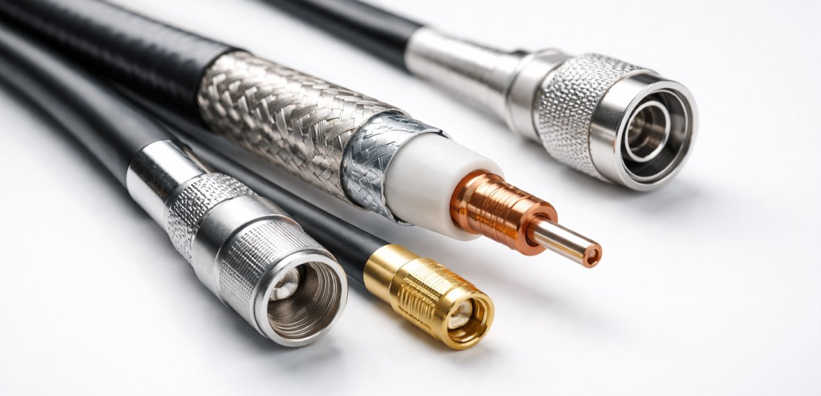
RF cables, or radio frequency cables, are specialized coaxial transmission lines designed to carry high-frequency electrical signals, typically from a few megahertz up to tens of gigahertz, between two components in a circuit or system. The word “coaxial” describes their construction: a central conductor surrounded by a dielectric insulator, which is then surrounded by a cylindrical outer conductor (the shield), all wrapped in a protective outer jacket.
This concentric layered structure is not aesthetic. It is functional. The outer conductor acts as a Faraday cage around the signal-carrying inner conductor, containing the electromagnetic field within the cable and preventing external electromagnetic interference from entering. This shielding is what makes RF cables fundamentally different from standard multi-conductor cables, and it is why they are the correct choice wherever signal quality and EMI protection are non-negotiable requirements.
The impedance of an RF cable, typically 50 ohms for most RF and microwave applications or 75 ohms for broadcast and video systems, is determined by the ratio of the outer conductor diameter to the inner conductor diameter and the dielectric constant of the insulating material between them. Maintaining this impedance consistently along the cable’s entire length is critical. Any discontinuity, whether from a physical bend, a manufacturing defect, or a poorly terminated connector, creates an impedance mismatch that causes a portion of the signal to reflect back toward the source. In sensitive systems, these reflections degrade performance measurably.
Understanding the four layers of an RF cable gives buyers a practical framework for evaluating quality:
The center conductor carries the signal. It is typically made from copper or copper-clad steel. Solid copper offers lower resistance and better conductivity. Copper-clad steel offers improved tensile strength, which matters in applications involving mechanical stress or frequent flexing. Silver-plated copper is used in high-frequency applications where skin effect concentrates current flow at the conductor surface, because silver has slightly better surface conductivity than copper.
The dielectric separates the center conductor from the outer shield and determines the cable’s electrical characteristics including impedance, capacitance, and velocity of propagation. Polyethylene (PE) is the standard dielectric for most applications. Expanded or foam polyethylene reduces dielectric losses at higher frequencies. PTFE (Teflon) is used in high-temperature or high-frequency applications because of its excellent dielectric properties and thermal stability.
The outer conductor serves dual functions: it is the return path for the signal current and it provides EMI shielding. Construction varies significantly: braided shields offer flexibility and reasonable shielding effectiveness; foil shields provide near-complete coverage but less flexibility; combination foil-plus-braid shields optimize both. Spiral or serve shields offer maximum flexibility but reduced shielding, making them suitable for applications requiring repeated flexing.
The jacket protects the cable from environmental factors including moisture, abrasion, chemical exposure, and UV radiation. PVC is standard for indoor applications. Polyurethane or polyethylene jackets are preferred for outdoor or harsh environments. In military and aerospace applications, specialized fluoropolymer jackets provide resistance to extreme temperatures, fuels, and hydraulic fluids.
Signal integrity in RF systems is not a theoretical concern. It has direct, measurable consequences in real systems. In a radar system, insertion loss in the RF cable between the antenna and the receiver translates directly to reduced detection range. A cable that introduces 3 dB of loss halves the received signal power. In a wireless base station, impedance mismatches in the feeder cable cause standing waves that reduce transmitted power and can stress the transmitter hardware. In defence communication systems, degraded signal quality can mean the difference between a reliable link and a failed one at the worst possible moment.
The three most important signal integrity parameters that RF cable performance directly affects are:
This is the signal power lost as it travels through the cable. It increases with frequency, meaning a cable that performs adequately at 1 GHz may introduce unacceptable losses at 10 GHz. Cable datasheets specify insertion loss in dB per unit length at defined frequency points. Buyers sourcing cables for high-frequency applications must check the loss specification at their operating frequency, not just the headline figure at low frequency.
VSWR is the measure of impedance matching quality. A perfect cable would have a VSWR of 1:1. Real cables have values above this. Higher VSWR means more signal reflection and less efficient power transfer. Military and precision RF systems typically specify maximum acceptable VSWR values, and cables that exceed this limit fail system requirements regardless of other performance characteristics.
This measures how effectively the outer conductor prevents external electromagnetic interference from coupling into the signal path, and how much RF energy is contained within the cable rather than radiating outward. Shielding effectiveness is specified in dB, with higher values indicating better shielding. Applications in electromagnetically dense environments, such as shipboard electronics or aircraft avionics, require cables with high shielding effectiveness to maintain clean signal paths.
RF cables are not one product. They span a broad range of constructions, sizes, and performance grades, each suited to specific applications. Understanding the major categories prevents specification errors that are costly to correct after procurement.
Semi-rigid cables use a solid tubular outer conductor made from copper or aluminum. This construction gives them excellent shielding effectiveness and stable, repeatable electrical characteristics. The trade-off is that they are permanently formed during installation and cannot be reconfigured without specialized tooling. Semi-rigid cables are used in laboratory instruments, radar systems, satellite equipment, and any application where consistent electrical performance outweighs routing flexibility.
Flexible cables use braided or spiral outer conductors and flexible dielectric materials that allow the cable to be routed around obstacles and connected to components with physical offset. They are the workhorse of most installed RF systems because they can accommodate real-world routing requirements. Performance varies significantly across the flexible cable category. Budget flexible cables sacrifice shielding effectiveness and loss performance for cost. Military-grade flexible cables maintain tight specifications even at high frequencies, using high-strand-count silver-plated braids and low-loss dielectrics.
Phase-stable cables are engineered to maintain consistent electrical length across temperature variations and mechanical flex cycles. This matters in systems like phased-array antennas and calibration setups where phase relationships between multiple cable paths must remain stable. Low-PIM (Passive Intermodulation) cables are designed to minimize intermodulation distortion caused by nonlinear behavior in the cable materials, which is a specific concern in high-power cellular and base station systems where multiple carriers share the same antenna path.
Beyond standard coaxial construction, triaxial cables add a second shield layer for enhanced isolation, used in measurement and instrumentation. Twinaxial cables carry two conductors within a shared shield, useful for differential signaling in high-speed data applications where balanced signal pairs are required.
RF cables are specified by standard designations that communicate their construction and electrical characteristics. Understanding these designations saves significant time during specification and procurement.
RG designations are the most widely recognized cable identifiers in the RF world. Common examples include RG-58 (50 ohm, thin, flexible, used in general RF applications), RG-59 (75 ohm, used in video and CATV), RG-8 (50 ohm, larger diameter, lower loss for longer runs), and RG-316 (50 ohm, very small diameter, PTFE dielectric, good high-frequency performance). The RG number alone does not guarantee performance. Different manufacturers produce RG-designated cables with varying quality levels, so a COA and datasheet review remains necessary even when ordering a standard designation.
Military specification cables are defined under the MIL-DTL-17 standard, with cable types designated by the M17 prefix. These cables are manufactured to controlled specifications covering conductor dimensions, dielectric properties, shielding construction, and electrical performance parameters. Sourcing M17-designated cables from authorized distributors who can provide traceability documentation is essential for defence and government contract applications. Arise-O-Tech specializes in the supply of Mil-grade connectors, cables, and accessories specifically for defence and rugged electronics applications.
LMR-designated cables are widely used in wireless communication infrastructure including cellular base stations, GPS, Wi-Fi, and broadband wireless. The LMR number broadly indicates the cable diameter and loss performance class. LMR-400, for example, is a 50-ohm cable with significantly lower loss per unit length than RG-8, making it the preferred choice for antenna feeder runs where minimizing path loss is a priority.
Selecting an RF cable for a specific application involves balancing multiple performance parameters against operational constraints. The following framework structures this decision into four evaluation dimensions.
Define your operating frequency range and your maximum acceptable insertion loss. For the loss calculation: multiply the cable’s loss per unit length at your operating frequency (from the datasheet) by the required cable length. Add connector insertion loss at both ends. If the total exceeds your loss budget, you either need a lower-loss cable or a shorter run.
Confirm your system’s impedance requirement (50 ohms for most RF and microwave systems, 75 ohms for video and broadcast). Verify that the cable, connectors, and all mating components share the same impedance. A 50-ohm cable terminated with 75-ohm connectors creates an impedance discontinuity at every interface.
Consider the installation environment. Will the cable be routed in conduit, exposed to weather, subject to repeated flexing, or installed in a high-vibration environment? Will it need to operate across a wide temperature range? Cables for airborne, shipboard, or military vehicle applications must meet significantly more demanding mechanical and environmental specifications than indoor laboratory cables.
For defence, government, and certain industrial applications, cable compliance with specific standards such as MIL-DTL-17 or industry-specific requirements may be contractually mandated. Procuring cables from RF cables distributors in India who can provide full traceability, manufacturer certifications, and test documentation is not optional in these cases. Arise-O-Tech’s products and services are specifically oriented toward defence, aerospace, and industrial customers where compliance documentation is a baseline requirement.
The RF cable market in India includes a wide range of suppliers from authorized distributors of international brands to grey-market traders selling uncertified products at reduced prices. For non-critical consumer applications, the distinction may have limited practical consequence. For defence, aerospace, telecommunications infrastructure, and industrial instrumentation, it matters enormously.
Counterfeit and substandard RF cables are a documented industry problem globally. These cables may pass visual inspection and even basic continuity checks, but fail on shielding effectiveness, impedance stability, insertion loss performance, or long-term reliability under operating conditions. In a system where a failed cable means lost communication or mission failure, the cost saving on procurement is vastly outweighed by the operational and reputational consequence.
Authorized distributors who source from verified manufacturers can provide:
Arise-O-Tech serves as India’s leading distributor for rugged electronics components including RF connectors, Mil-grade connectors, cables, and accessories. Their focus on the defence, aerospace, land, and sea segments reflects the specific supply chain discipline these applications require. Working with an established RF cables supplier who understands the application context, not just the catalogue, is a meaningful risk reduction in high-stakes procurement.
RF cables are only as good as their terminations. RF connectors are the interface between a cable and a component, and every connector junction is a potential source of impedance mismatch, signal reflection, and mechanical failure. Common RF connector series include SMA, N-type, BNC, TNC, SMA, and 2.92mm (K) connectors for millimeter-wave applications.
The selection logic for RF connectors mirrors the cable selection framework: operating frequency range, power handling requirement, mechanical robustness, and environmental sealing all factor into the correct connector choice. Arise-O-Tech’s RF connectors include Mil-grade options designed for the demanding mating cycles, vibration levels, and environmental exposure conditions of defence and rugged applications.
Defence and aerospace applications represent the most demanding RF cable environments. Cables in these applications must perform reliably across extreme temperature ranges, survive high vibration and shock loads, resist fuels, hydraulic fluids, and other harsh chemicals, and maintain consistent electrical performance over long service lives often measured in decades.
The consequence of cable failure in these environments is not just a system outage. In airborne systems, it can affect flight-critical communication or navigation. In military communication systems, it can compromise operational security or mission success. This is why MIL-DTL-17 specifications exist, and why procurement from suppliers with the capability to source and document genuine MIL-spec cables is a genuine operational requirement rather than a procurement preference.
Arise-O-Tech’s service portfolio includes repair and maintenance of electronics equipment alongside component distribution, which reflects a deeper operational understanding of the defence electronics ecosystem than pure catalogue distribution provides. This matters when an application requires not just supply of cables but informed advice on specification, installation, and system integration.
RF cables sit at the foundation of every communication, radar, navigation, and wireless infrastructure system in operation today. They are not passive accessories. They are active performance components whose selection, quality, and installation directly determine whether a system meets its design specifications or falls short of them.
The key takeaways from this guide are practical. First, RF cable selection requires matching the cable to the specific frequency, loss budget, impedance, mechanical, and environmental requirements of the application. Second, visual quality and brand recognition are insufficient substitutes for documentation, compliance certification, and traceability, especially in defence and mission-critical applications. Third, the difference between a reputable RF cables supplier who understands your application and a general catalogue distributor is not just a procurement preference. In demanding applications, it is a risk management decision.
For engineers and procurement professionals working in defence electronics, rugged systems, avionics, or industrial communication in India, sourcing from a distributor with genuine application expertise, verified supply chains, and Mil-grade capability is the starting point for getting RF cable procurement right. Explore Arise-O-Tech’s full product range and get in touch with their team to discuss your specific cable and connector requirements.
FAQ
What is the difference between a 50-ohm and a 75-ohm RF cable?
The impedance value of an RF cable is matched to the impedance of the source and load it connects. 50-ohm cables are the standard for most RF and microwave applications including radar, military communications, test equipment, and wireless infrastructure because 50 ohms represents a practical compromise between power handling capacity and signal loss. 75-ohm cables are the standard for broadcast video, CATV, and cable television distribution systems where the priority is minimizing signal loss over long runs at the expense of some power handling capacity. Using a 50-ohm cable in a 75-ohm system, or vice versa, creates an impedance mismatch at every interface that degrades performance. Never substitute one for the other without confirming system impedance requirements.
How do I calculate the right cable length to minimize insertion loss?
The cable manufacturer’s datasheet specifies insertion loss in dB per 100 meters (or per 100 feet) at defined frequency points. Multiply the loss per unit length at your operating frequency by the required cable length, then add the insertion loss of the connectors at both ends (typically 0.1 to 0.3 dB per connector depending on frequency and connector quality). Compare the total against your system’s allowable path loss. If the total exceeds the budget, either select a lower-loss cable, reduce the cable length if possible, or add an amplifier to compensate. For high-frequency applications, always calculate loss at the highest frequency in your operating band, not at a lower representative frequency.
What makes an RF cable suitable for military or defence applications?
Military-grade RF cables must meet the requirements defined in MIL-DTL-17 or other applicable military specifications. These cover dimensional tolerances for the conductor and dielectric, shielding construction and coverage percentage, electrical performance parameters including impedance, attenuation, and VSWR across the required frequency range, mechanical performance under vibration and shock testing, and environmental resistance to temperature extremes, moisture, fuels, and other harsh chemicals. Beyond the cable itself, procurement for defence applications requires full traceability documentation, manufacturer certificates, and sourcing from authorized distributors who can support compliance verification. Arise-O-Tech focuses specifically on Mil-grade connectors and cable supply for defence segment customers.
What is the maximum frequency range for standard RF cables?
Standard coaxial RF cables are used across a very wide frequency range. Common flexible cables like RG-58 or LMR-400 are specified up to 1 to 3 GHz for practical use, though they can operate at higher frequencies with increased loss. Semi-rigid cables and precision flexible cables using PTFE dielectrics are routinely specified to 18 GHz, 26.5 GHz, or higher. Millimeter-wave applications up to 110 GHz require specialized very small-diameter cables and precision connectors. As a general rule, cable loss increases with frequency, and the practical upper frequency limit is the point where insertion loss becomes unacceptable for the application rather than a hard physical cutoff.
How should RF cables be installed to maintain signal integrity?
The most common installation errors that degrade RF cable performance include bending the cable below its minimum bend radius (which deforms the shield and dielectric, creating impedance discontinuities), over-tightening cable ties or clamps (which can crush the dielectric), and sharp kinks near connector terminations (which stress both the cable and the solder or crimp joint). Cables should be routed with gentle curves, supported at appropriate intervals to prevent sag, and terminated with correctly matched connectors using proper tooling. For flexible cables, the minimum bend radius is typically specified on the datasheet as a multiple of the cable’s outer diameter. For semi-rigid cables, bending must be done with appropriate forming tools and is permanent.
What should I verify when receiving RF cables from a distributor?
On receipt, verify the cable’s part number and lot code against the order documentation. Check for physical damage including kinks, crush marks, or jacket damage. For MIL-spec or certified cable orders, confirm that the manufacturer’s test certificate or COA accompanies the delivery and matches the lot number on the cable reel or spool. For connector-terminated cable assemblies, visually inspect the connector terminations for correct seating and no evidence of cold solder joints or incomplete crimps. If performing incoming inspection, measure insertion loss and VSWR on a sample from the lot using a vector network analyzer (VNA) and compare against the cable’s published specification. Any lot that fails to meet specification should be quarantined and returned with supporting test data.